Bently Nevada 2300/20to DCS
A correct local vibration value can still reach the DCS as an underrange alarm, a frozen number or a signal that stops rising before full scale.
Bently Nevada identifies DCS interfacing as a use of the 2300/20 configurable current output. This review addresses transfer of a selected measurement through 4–20 mA, not full-waveform diagnostic data.
Before replacing the monitor or changing calibration, establish which device supplies power to the current loop. Confirm that the selected DCS connection accepts a powered current output, then check burden, grounding and configuration.
Start with the exact output specification.
The 105M0340 Rev. AD datasheet specifies two internally powered current outputs for the 2300/20 and excludes an externally powered loop. Output variable selection is configurable; the default clamp is 2 mA and can be changed. Output feedback determination is unavailable. The 2300/25 instead has an SPA interface.
Do not infer output type from a familiar connector, an old cabinet drawing or a spare described only as “2300.” Read the complete nameplate and compare the exact replacement with the installed configuration.
Identify the power source at the actual terminals.
The useful question is whether the chosen receiving terminals inject loop power. A powered backplane does not automatically make every analog input unsuitable. Conversely, terminals intended to power a two-wire transmitter can introduce a second supply.
Obtain the DCS card number, terminal-base number, wiring diagram and channel mode. Trace marshalling links, barriers, isolators and any cabinet supply. Vendor terms such as “active” and “passive” are not consistent enough for approval.
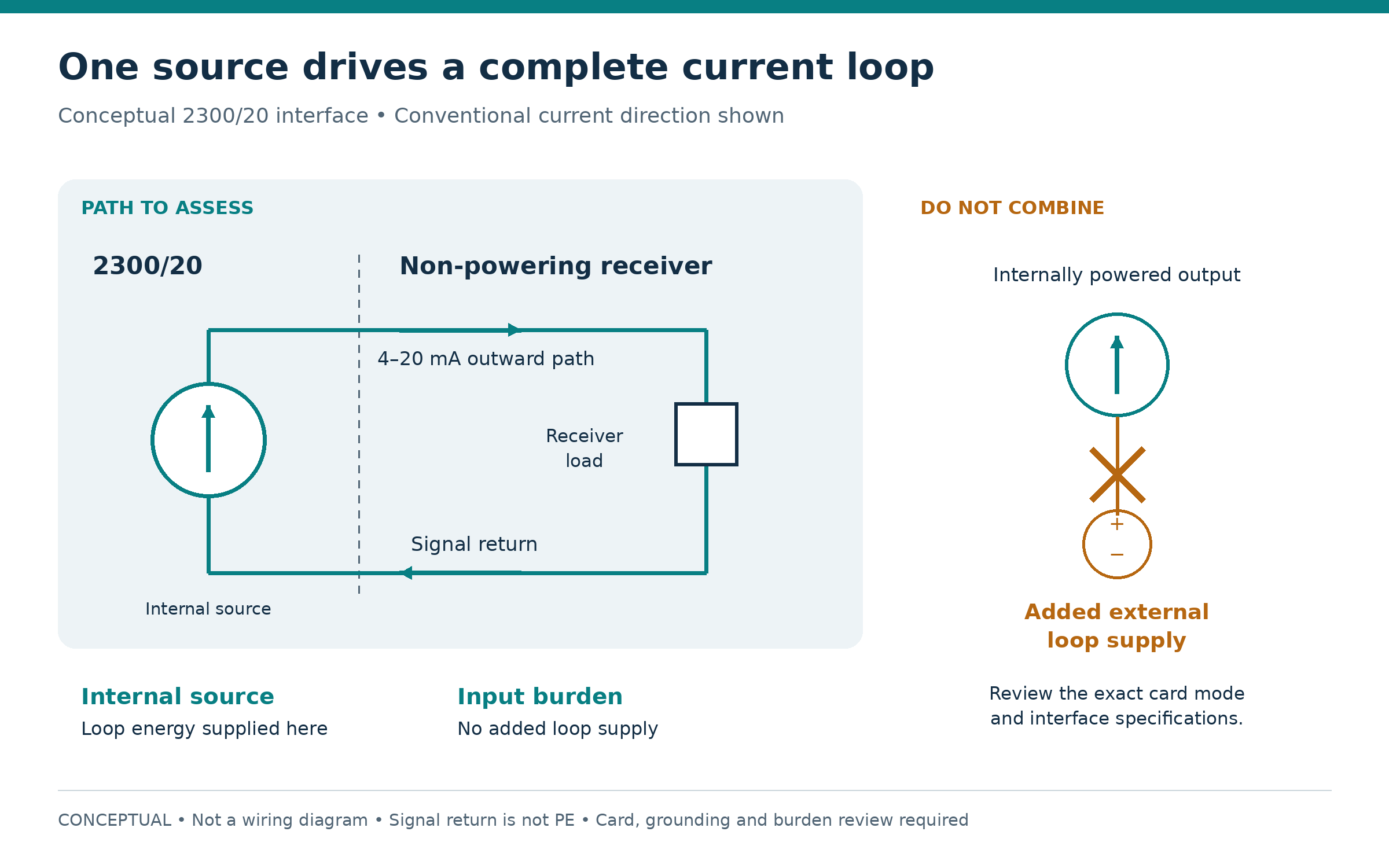
If the card manual documents a suitable non-powering receiving path, assess that path against all remaining requirements. If the only approved receiving path supplies loop power, specify an interface with a suitable non-powering input and a compatible output. An isolator still requires review of burden, power arrangement, isolation, grounding, accuracy, response, fault transfer and area approval.
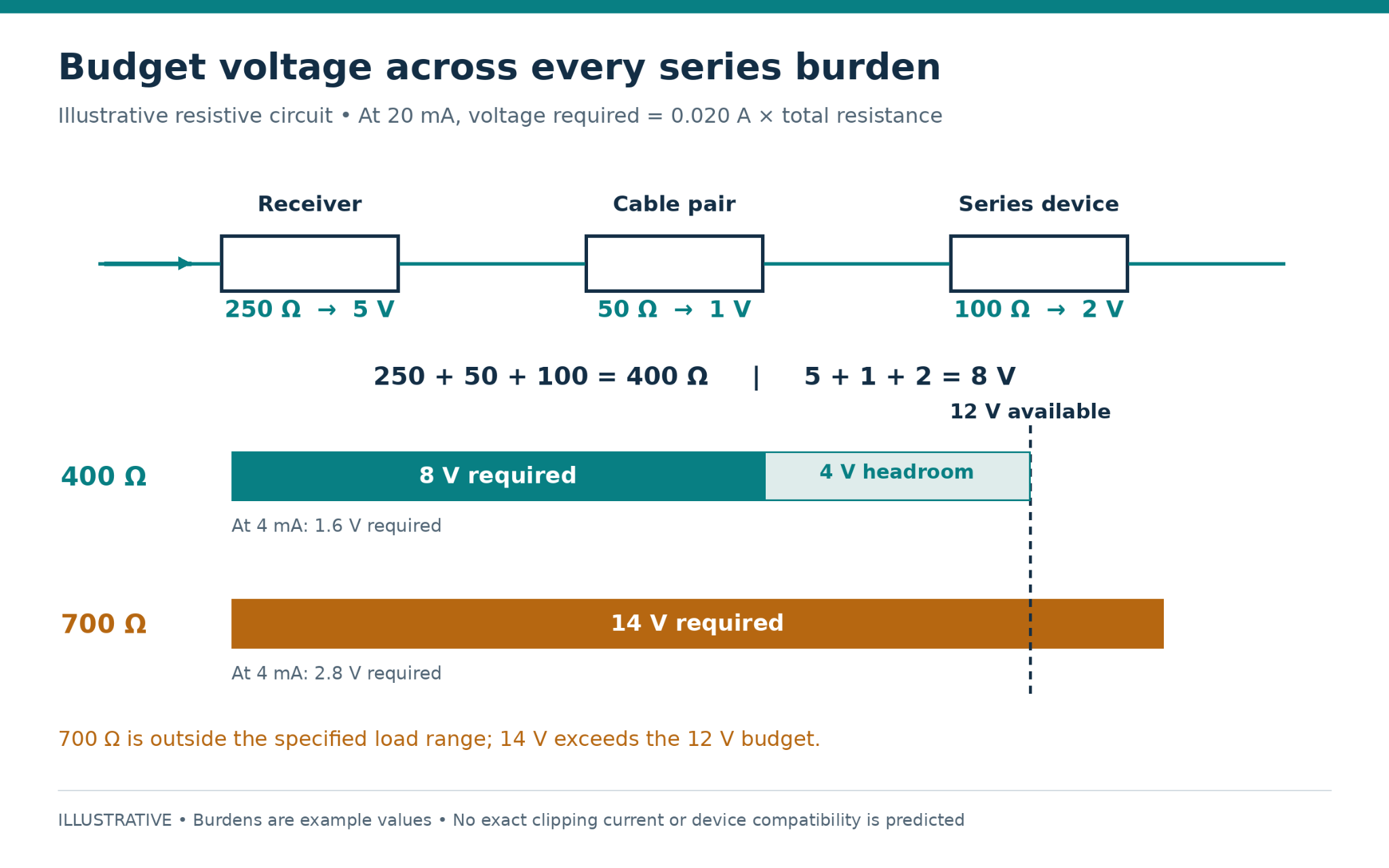
Calculate the complete voltage burden.
A current source needs voltage to force current through the total loop load. Include the receiver, both cable conductors, terminals and every series component. Use documented maximum values where available, including temperature effects.
Let the fault pattern guide the next check.
Check continuity, polarity, terminals, protection devices and receiving configuration. Do not add cabinet power as an experimental cure.
Compare actual current with the configured clamp and channel status. Preserve the distinction between diagnostic current and valid vibration.
Investigate compliance headroom, interface limits and output saturation. Compare requested value, measured current and loop burden.
Check selected variable, channel, range, units and amplitude convention: RMS, peak and peak-to-peak are different.
Inspect DCS raw scaling, range handling and display limits before replacing field hardware.
Time-correlate raw input, quality flags, switching and maintenance. Review return paths, shield termination and isolation.
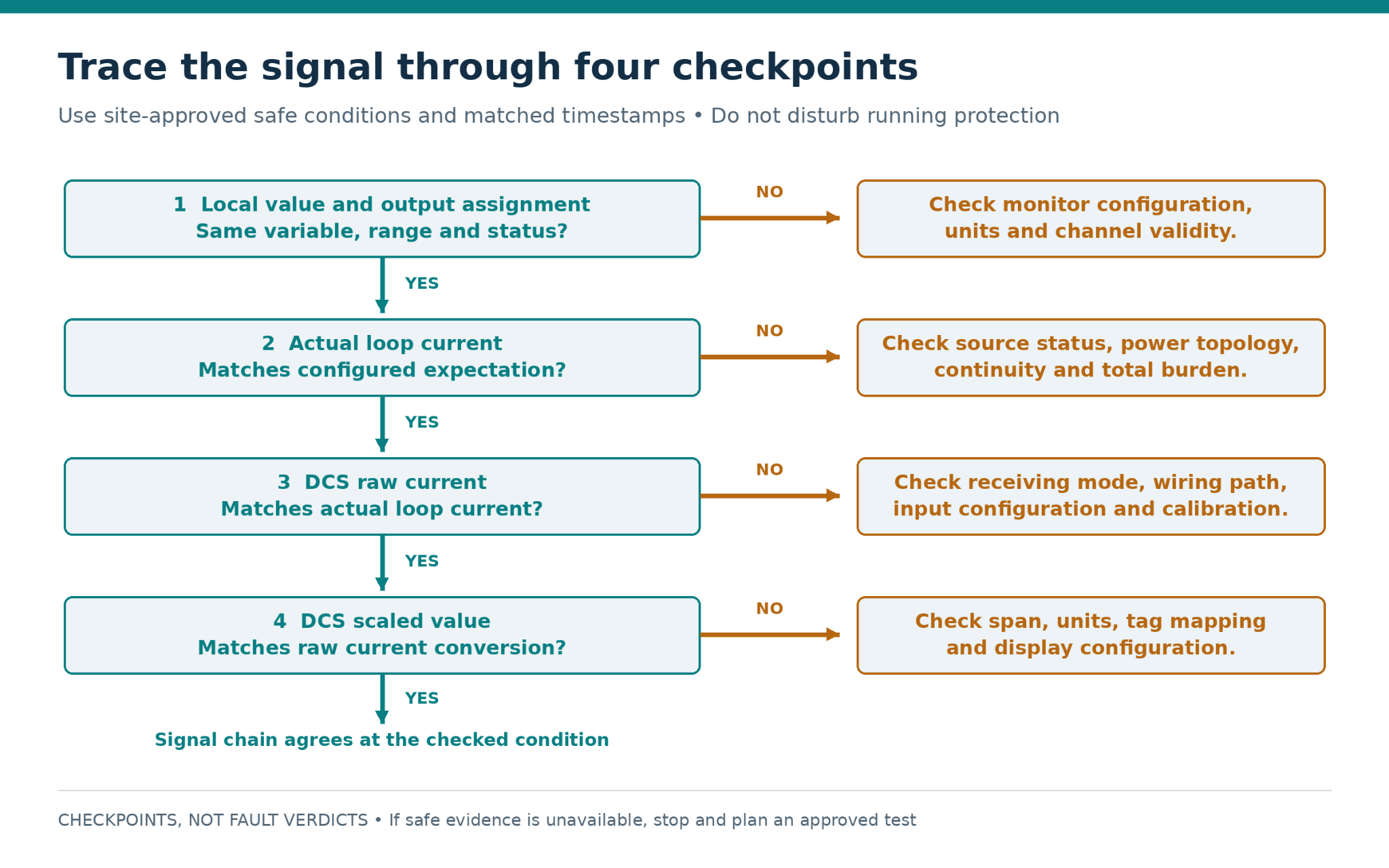
Prove each part of the path under an approved plan.
Establish consequences for trips, interlocks, alarms and operations before opening a loop or applying a test signal. Preserve the current configuration, identify the exact path, define authorization and restoration, and stop at documentary review if a safe test state cannot be established.
- Prove the receiving path separately with a correctly configured calibrator. Source and simulate modes are not interchangeable.
- Verify monitor-side transfer using the applicable OEM procedure and approved known conditions.
- Compare monitor measurement, independent current, DCS raw input and engineering value at several points.
- Verify approved fault indications separately from normal scaling, then record as-found and as-left settings.
For an illustrative 0–25 mm/s range, 4, 12 and 20 mA correspond to 0, 12.5 and 25 mm/s. These are examples, not a prescribed monitor configuration. The conversion is lower range + [(current − 4 mA) ÷ 16 mA] × engineering span.
Related Amikong product pages.
Ask for written confirmation of the offered part number, condition, lead time, warranty, inspection and documents. Final installation suitability remains subject to the applicable OEM documents and the responsible site engineer’s approval.
Related Bently Nevada customer records.
Common interface questions.
Can the 2300/20 connect directly to a DCS analog input?
Potentially, after the exact receiving connection is verified for power behavior, burden, polarity, common-mode limits and grounding. Matching 4–20 mA ranges alone is insufficient.
Does a powered DCS card always require an isolator?
No. Card power and loop power are different questions. Use the installed card and terminal-base diagram to identify whether the chosen signal connection injects field power.
Why does a successful 4 mA check not prove the loop?
Voltage demand rises with current. Low-end success can conceal a high-end limit and says little about span, selected variable or fault handling.
Should low diagnostic current be scaled as negative vibration?
Normally it should trigger the defined quality and fault handling. Establish the configured diagnostic behavior and DCS thresholds before interpreting it.
Can the two outputs be combined to feed one input?
Do not parallel current outputs. If several destinations require the same signal, review an approved distribution interface and define failure behavior.
Does a correct monitor reading prove delivery to the control room?
No. Verify actual current and the DCS raw value to separate an output-path problem from scaling or tag configuration.
Can a replacement be selected from the connector alone?
No. Match the full model, options and required output function, then review configuration and approvals.
What should be included in an article-specific enquiry?
Send the complete 2300/20 option code, DCS card and terminal-base identifiers, quantity, destination, required date, nameplate photographs and the specific loop-power question.
Send the complete loop identity.
Provide the monitor model and option code, a clear nameplate photo, DCS card and terminal-base identifiers, proposed diagram, units, configured ranges, quantity and required-by date.
Technical sources
- Baker Hughes / Bently Nevada — 2300/20 and 2300/25 Vibration Monitors, Datasheet 105M0340 Rev. AD. DCS application on printed page 1; output specifications on printed page 5.
The DCS receiving-card discussion is a general engineering review principle, not a statement that the 2300/20 is paired with a specific DCS manufacturer. Check the official manual for the exact installed DCS card and terminal base. The circuit calculations and diagnostic sequence are illustrative and do not represent a tested customer installation.